
Views: 0 Author: Site Editor Publish Time: 2026-10-24 Origin: Site


Did you know a microscopic slip in embedded steel can eventually compromise an entire bridge?
Proper concrete bonding demands exact indentation measurements. Shallow grooves will inevitably cause dangerous slippage under heavy loads. This jeopardizes the structural integrity of the concrete matrix. In this comprehensive guide, you will learn how to accurately confirm indent depth on indented PC strand samples. We will explore practical laboratory techniques to ensure your materials meet strict global safety tolerances.
Indent depth acts as a critical quality metric that directly dictates the mechanical bond strength between the prestressing cable and the concrete matrix.
Confirming this depth requires specific and calibrated tools. These range from mechanical depth micrometers equipped with needle-point anvils to advanced optical profile projectors.
Measurements must strictly adhere to international codes like ASTM A886 and EN 10138 to guarantee load-bearing capacity and overall structural safety.
Proper sampling methods are non-negotiable for accurate readings. This includes meticulous solvent cleaning and multi-point verification across different pitches.
High-quality materials must maintain consistent indent geometry without sacrificing their low relaxation properties or dynamic fatigue resistance.
An Indented PC Strand, also known as a Prestressed Concrete Strand, is a specialized high-tensile steel cable utilized primarily in prestressed and post-tensioned concrete structures. Typically constructed in a 7-wire configuration, it features a straight central core wire tightly surrounded by six helically spun outer wires. Unlike standard smooth cables, the outer wires of an indented strand possess mechanically pressed grooves along their surface. Engineers specifically design these geometric modifications to maximize the mechanical interlocking between the steel and the surrounding concrete.
Producing these specialized cables requires immense metallurgical precision. High-carbon steel wire rods are first chemically descaled and cold-drawn. This process elevates their ultimate tensile strength to industry benchmarks, often reaching 1860 MPa. Before the individual wires are stranded together, the outer wires pass through a series of specialized profiling rollers. Hardened tungsten carbide rollers press a specific indentation pattern into the steel under extreme pressure. Following this profiling, the Prestressing Strand undergoes a thermomechanical stabilization treatment. This crucial step relieves internal manufacturing stresses and stabilizes the crystalline structure.
Standard plain variants rely primarily on adhesion and friction for concrete bonding. In contrast, indented versions introduce a highly effective third mechanism known as mechanical interlock. Civil engineers deliberately specify indented profiles for applications where enhanced anchorage is mandatory. This is especially true when transmission lengths must be drastically minimized. Such applications frequently include hollow-core slabs, heavy-duty railway sleepers, and precast concrete beams lacking end-anchorage devices.
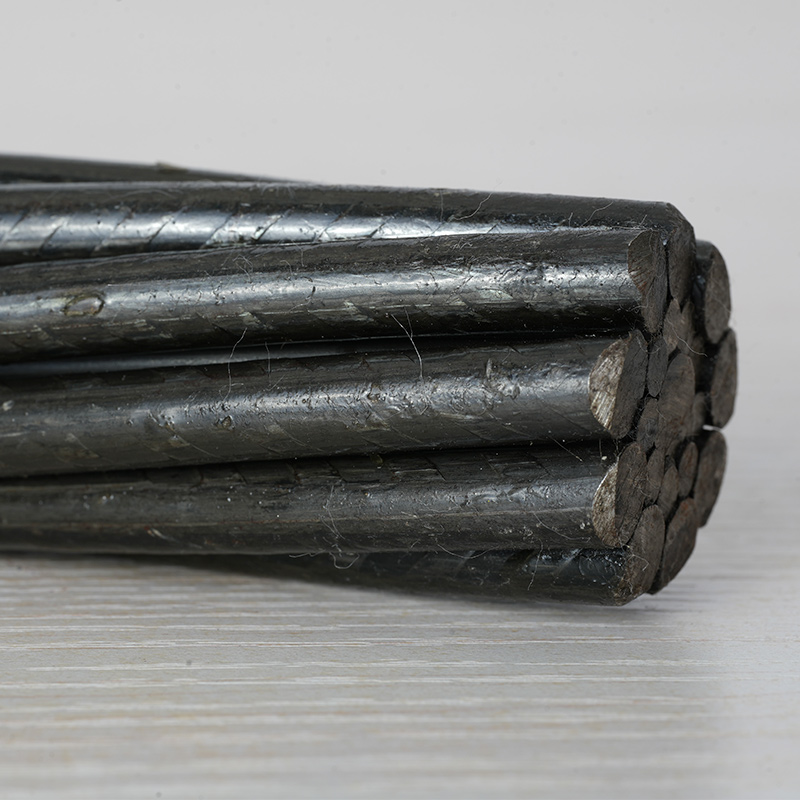
The geometry of these surface grooves is never arbitrary. It is a meticulously calculated engineering parameter. Ultimately, the depth of these indentations governs the structural viability of the entire concrete member.
Achieving the perfect groove is a delicate balancing act. Metallurgists often refer to this as the Goldilocks principle of wire drawing.
If the indent depth falls below the specified tolerance, the strand fails to create sufficient mechanical interlocking with the concrete. This shallow profile leads to strand slippage under heavy dynamic loads. The result is a sudden loss of prestress and potential catastrophic failure. Conversely, pressing the indents too deeply into the wire forms severe stress concentration points. Deep notches inadvertently reduce the effective cross-sectional area of the steel. This significantly lowers the ultimate breaking load and renders the high-carbon wire unacceptably brittle.
Indent geometry directly correlates to the transmission length and pull-out resistance within concrete members. This includes the depth, pitch, and edge shape. A highly controlled depth ensures that the transfer of stress from the steel to the concrete occurs precisely within the designed spatial limits. When QA inspectors evaluate an Indented Steel Strand, confirming this specific depth remains the primary method for validating its real-world pull-out strength capabilities.
Looking at recent shifts in the heavy construction sector, there is a clear migration toward zero-defect tolerances in mega-infrastructure projects. Global regulatory bodies are tightening compliance audits across the board. The era of relying solely on outdated manual spot-checks is fading.
Modern civil engineering demands digitized and traceable quality assurance data. Leading manufacturers are now integrating continuous inline 3D laser scanning into their production lines. This automated metrology captures thousands of data points per second, ensuring every single meter of the coil meets exact geometric specifications. For procurement teams, sourcing materials backed by this level of digital traceability is becoming a standard requirement to mitigate structural liability.
To ensure global safety and construction consistency, international regulatory bodies have established strict parameters for indent geometry. Procurement managers and lead engineers must verify that their sourced materials align perfectly with the specific standards dictated by regional building codes.
Different standards dictate varying acceptable ranges for indent depth, width, and pitch. For instance, ASTM A886 outlines the specifications for indented seven-wire prestressing steel strand in North America. Meanwhile, EN 10138-3 provides the regulatory framework for European markets.
Typically, the nominal indent depth ranges between 0.05 mm and 0.15 mm. This range heavily depends on the nominal diameter of the wire and the specific standard applied. Quality control teams must always consult the most current version of the relevant standard for exact project tolerances.
Compliance is never a one-time check. Standards explicitly dictate the frequency of quality control testing. A reputable manufacturer or third-party laboratory must pull samples from a coil at designated intervals. A common practice is testing one sample per 10-ton batch. This confirms that the profiling rollers have not worn down and that the specifications remain perfectly uniform throughout the production run.
Quantifying a microscopic groove on a curved steel surface requires specialized and highly calibrated equipment. Standard workshop calipers or flat-anvil micrometers will yield wildly inaccurate results.
These remain the traditional mainstays of the QA laboratory. However, standard micrometers are useless for this specific task. Inspectors must utilize specialized depth micrometers equipped with needle-point or fine conical anvils. The probe tip must be narrow enough to reach the absolute bottom of the indent valley without resting on the sloping side walls.
For superior accuracy, laboratories frequently utilize optical profile projectors or shadowgraphs. These machines project a highly magnified silhouette of the wire onto a calibrated grid screen. By analyzing this shadowgraph, technicians can measure the precise depth of the indent alongside the pitch distance and edge angles. This optical method effectively eliminates the physical variables associated with manual probing.
Modern non-destructive testing methods have introduced 3D laser scanners to the industry. These advanced devices map the surface topology of the strand in three dimensions. By generating a digital twin of the physical sample, advanced software algorithms automatically calculate the average indent depth across hundreds of data points. This entirely removes human operator error from the equation.
For QA inspectors and laboratory technicians, following a strict Standard Operating Procedure is vital. It ensures the generation of valid and legally binding compliance reports.
Start by cleanly shearing a 500mm to 1000mm length from the coil. Avoid using abrasive cutting wheels. The localized heat generated by a grinder can warp the micro-structure of the steel. Next, grab a lint-free cloth and an industrial solvent like acetone. You must scrub the wire meticulously. Even a microscopic speck of residual drawing lubricant, rust-preventative oil, or airborne dust trapped in the groove will artificially raise the floor of the indent. This completely skews the depth reading.
A curved wire will naturally roll under the pressure of a micrometer. Therefore, you must clamp the sample securely in a precision steel V-block resting on a flat granite surface plate. This professional setup ensures the longitudinal axis of the wire remains perfectly horizontal and stationary during the delicate measurement process.
Using a calibrated needle-point depth dial indicator, the operator must first establish the zero reference point. Achieve this by resting the gauge on the nominal un-indented cylindrical surface of the wire immediately adjacent to the groove. Once zeroed, carefully lower the probe into the deepest central point of the indentation. Listen or feel for the click of the micrometer ratchet to ensure consistent contact pressure. The gauge must be held perfectly perpendicular to the wire axis to avoid cosine errors.
A single measurement is statistically insignificant. Inspectors must measure multiple indents along the pitch length and across different outer wires of the 7-wire strand. Industry best practices require taking a minimum of 10 separate measurements. You then calculate the mean average depth to account for minor manufacturing variances.
Finally, log all raw data, calculated averages, and standard deviations into the laboratory information management system. This data forms the foundational basis of the Mill Test Reports required by procurement managers and site engineers.
Securing precise measurements requires rigorous metrological discipline. Even minor deviations in testing methodology can lead to false readings. This causes QA inspectors to either reject compliant batches or approve dangerously non-compliant materials.
One of the most frequent errors in quality control labs is utilizing a standard flat or oversized spherical probe tip. The indents on a prestressing wire are narrow and precisely engineered grooves. If the probe tip diameter exceeds the width of the indent valley, the anvil will rest on the upper slopes or edges of the groove rather than penetrating to the true bottom.
This geometric mismatch inevitably results in a falsely shallow depth reading. To avoid this, QA inspectors must use specialized depth micrometers equipped with needle-point anvils. The tip radius must be under 0.1mm and specifically calibrated for the pitch and width of the strand’s indentations.
Unlike measuring a flat steel plate, evaluating a cylindrical wire presents a significant baseline challenge. The surface of the wire continuously curves away from the measurement axis. Establishing a true zero point on the nominal surface is difficult. Any slight lateral movement of the micrometer will cause the probe to slide down the curvature, altering the baseline.
To mitigate this issue, rigidly secure the sample in a calibrated V-block. Furthermore, digital profilometers or optical shadowgraphs are highly recommended over manual micrometers. They can digitally map the curve and calculate the exact perpendicular depth from the theoretical outer diameter of the wire.
When utilizing manual depth micrometers, human error introduces significant variables. The amount of torque or downward pressure applied by the operator can compress the metal slightly or shift the instrument off-center. Inconsistent pressure across multiple measurements will yield a high standard deviation in the recorded data.
Implementing ratchet-stop micrometers helps standardize contact pressure. However, transitioning to automated optical testing methods removes operator tactile variability entirely. This ensures that every batch is measured against an objective standard.
Measurement Error | Primary Cause | Metrological Solution |
|---|---|---|
Falsely Shallow Reading | Probe tip too wide for indent valley. | Utilize a needle-point anvil micrometer with a tip radius under 0.1mm. |
Fluctuating Baselines | Wire rolling or shifting during test. | Secure the sample in a calibrated steel V-block clamp. |
High Standard Deviation | Inconsistent operator contact pressure. | Upgrade to ratchet-stop micrometers or automated optical profilometers. |
Environmental Skew | Thermal expansion of steel in warm labs. | Conduct measurements in a temperature-controlled QA environment typically maintained at 20°C. |
The engineering of an indented cable is a delicate balancing act. Manufacturers must maximize mechanical concrete adhesion while preserving the core metallurgical properties of the high-tensile steel. The physical indentations directly interact with the stress and relaxation characteristics of the wire.
Low relaxation properties are achieved through a specialized thermomechanical process. After the wire is drawn and stranded, it undergoes continuous induction heating while simultaneously being subjected to high mechanical tension. This stabilizing process realigns the crystalline structure of the steel. It significantly reduces the loss of stress over time when the strand is anchored in concrete.
However, the mechanical pressing of indents into the outer wires introduces localized plastic deformation. If the indent depth exceeds the parameters set by standards like ASTM A886, it creates severe stress concentration points. These deep grooves disrupt the uniform distribution of tension during the stabilizing process. Consequently, a poorly indented wire may fail to meet the strict relaxation limits required for a true Low Relaxation Strand. Top-tier materials mandate a maximum 2.5 percent stress loss at 1000 hours under 70 percent breaking load.
Fatigue resistance serves as another critical metric. This is particularly true in dynamic applications like railway sleepers or highway bridge girders. The geometry of the indent dictates how the wire handles cyclic loading. The depth and edge radius are the most critical factors here.
Perfectly rounded and uniformly deep indents allow stress to flow smoothly across the surface of the wire. In contrast, indents that are too deep or possess sharp and jagged edges act as micro-fissures. Under the rigorous 2-million cycle dynamic load tests mandated by international civil engineering codes, these sharp indentations become the origin points for fatigue cracks. This ultimately leads to premature strand failure. Manufacturers must carefully calibrate their profiling rollers to ensure that the indenting process enhances bond strength without compromising the ultimate tensile strength.
Procurement managers and lead engineers must exercise strict due diligence when sourcing high-tensile materials. The quality of the indentations is not merely a surface feature. It is a fundamental determinant of the structural viability of the concrete member. Selecting a reliable supplier requires looking beyond the price per metric ton and deeply analyzing their quality assurance infrastructure.
A reliable manufacturer will maintain total transparency regarding their in-house testing methodologies. When vetting a supplier, buyers should request detailed documentation on exactly how the facility confirms indent depth, pitch, and shape.
Key questions to ask during the auditing process include:
Does the facility utilize optical profile projectors or 3D laser scanners for indent verification?
At what frequency are samples pulled from the production line for metrological testing?
Is the testing laboratory certified by relevant third-party organizations like ISO 9001 or local national accreditation boards?
Suppliers who rely solely on outdated manual spot-checks pose a much higher risk of delivering coils with inconsistent indent profiles. This inconsistency can lead to catastrophic slippage on the job site.
The Mill Test Certificate is the definitive legal document verifying the mechanical and chemical properties of the steel batch. While all standard certificates will list the ultimate tensile strength, yield strength, and elongation parameters, a comprehensive certificate for indented products must go further.
Procurement teams must ensure that the document explicitly lists the physical geometric data of the indentations. This includes the average indent depth, the nominal pitch between indents, and the specific international standard to which these measurements conform. If a supplier is unable or unwilling to provide exact indent depth data alongside their standard tensile metrics, it is a clear indicator of inadequate quality control processes.
Finally, evaluate the supplier's traceability systems. High-quality manufacturers assign unique heat numbers and batch codes to every coil. This allows engineers to trace the final indented product all the way back to the raw steel wire rod. This level of traceability ensures that if a sample fails an indent depth confirmation test on the construction site, the exact production batch can be isolated and quarantined immediately.
Confirming indent depth is far more than a routine quality assurance checkbox. It acts as the frontline defense for overarching structural safety. Utilizing the proper metrological tools and strict laboratory methods prevents devastating wire slippage in the field. Accurate sample measurements guarantee strict compliance with international building codes.
When your project demands uncompromising quality, partnering with a proven manufacturer is non-negotiable. By rigorously reviewing test data to verify product quality, you effectively secure the lifespan and safety of your heavy construction projects. Explore the full range of certified, high-performance materials designed to meet exact engineering tolerances and ensure your next build stands the test of time.
Standard indent depths vary based on the specific international regulatory code and the nominal diameter of the wire. However, for most standard construction applications adhering to ASTM or EN specifications, the acceptable indent depth typically falls within a strict tolerance range of 0.05 mm to 0.15 mm.
While rough preliminary checks can be conducted on the construction site using specialized needle-point calipers or manual depth micrometers, these methods are highly prone to environmental and human error. Official confirmation for compliance reporting and structural safety verification requires the controlled environment and calibrated optical or digital equipment of a professional metrology laboratory.
The indenting process does slightly reduce the effective cross-sectional area of the outer wires. However, reputable manufacturers compensate for this minor reduction during the initial wire drawing and thermomechanical stabilizing processes. This ensures that the final indented product still safely meets or exceeds the required ultimate tensile strength and breaking load specified by engineering standards.
The primary difference lies in the surface geometry and the manufacturing process. Indents are mechanically pressed grooves that recede into the surface of the wire, creating valleys. In contrast, ribs are raised protrusions that sit above the nominal surface of the wire. Both geometries are designed to increase mechanical interlocking with concrete, but they are utilized based on different regional construction codes and specific engineering requirements.
Industry best practices and international standards dictate that samples should be tested at regular intervals, typically one sample per 10-ton to 15-ton batch. Additionally, profiling rollers must be inspected and calibrated at the start of every new production shift to account for mechanical wear on the tungsten carbide pressing tools.
An uneven indent pitch disrupts the uniform transfer of stress between the steel and the concrete matrix. This irregularity can create localized stress concentration points in the concrete, leading to micro-cracking around the strand. It also indicates a severe flaw in the manufacturing process, meaning the entire coil should be quarantined and re-tested for compliance.


